RF-101C
Ren Thang Machine
RF-101C
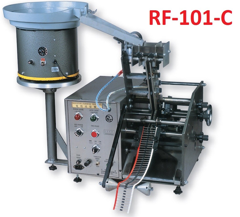
Axial Lead Forming Machine (Horizontal Mount with Smashing Spots)
電阻成型機-臥式打扁架高
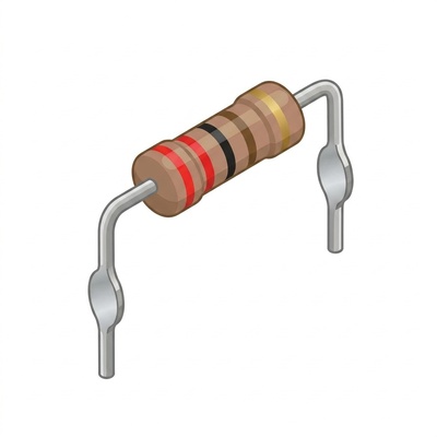
The RF-101C is an axial lead former specialized in punching fixed 2 mm lead smashing spots (flattened stand-off steps) at speeds up to 110 pcs/min. The flattened steps provide stable PCB standoff and uniform solder flow, with custom smashing tooling fabricated to customer drawings.
Processing & Feature Tags
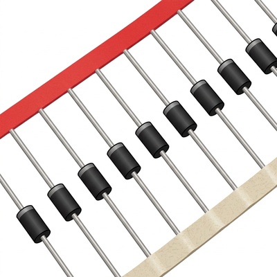
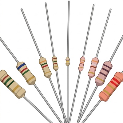
Odd Packaging
BDU
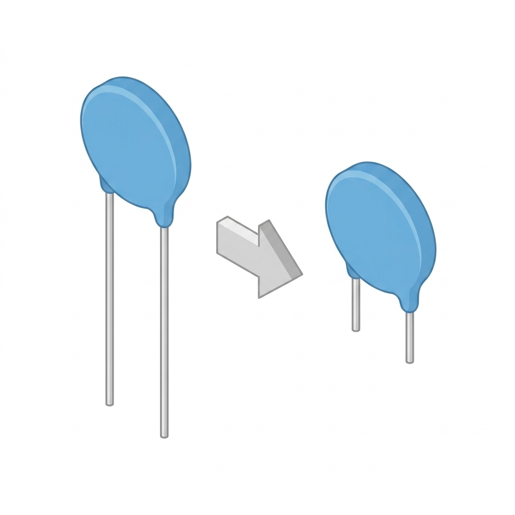
LSE
BOWL
ENGINEERING SPECIFICATIONS
Machine Specifications & Performance
Processing Capacity 6,600 pcs/小時 (110 pcs/分) / 6,600 pcs/Hour (110 pcs/min)
Power / Air Supply 110V/60Hz ; 220V/50Hz
Standard Tolerance ±0.3mm
Dimensions (L×W×H) 1140(L) x 730(W) x 750(H) mm
Net Weight 115 kgs
Catalog Page & Status
P.9 (Catalog_0009) • 在產 (Active)
【Key Machine Features & Advantages】
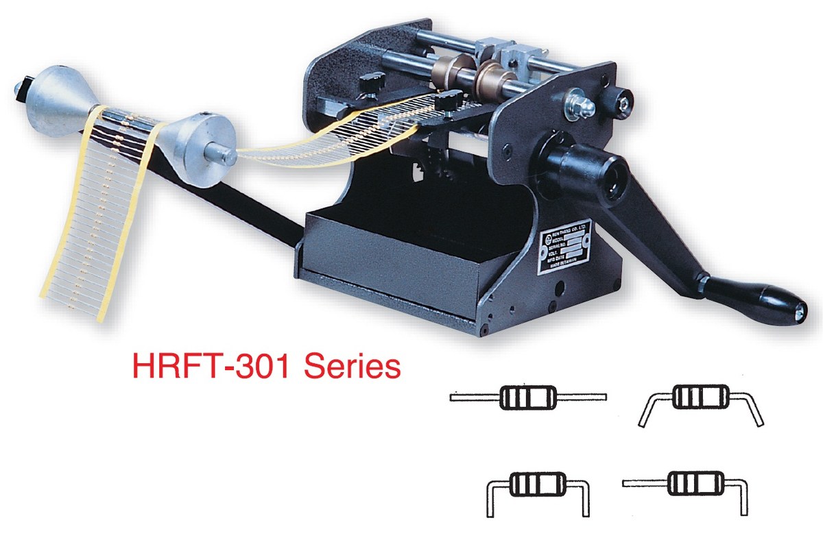
- Axial lead former for horizontal mount with lead smashing spots (flattened stand-off).
- Fixed 2 mm punching spots create mechanical steps on leads, providing firm PCB stand-off and uniform solder joints.
- Shares the proven high-rigidity machine chassis with RF-101M, configured with specialized smashing die sets.
- Accommodates axial resistors, diodes, and inductors with custom die manufacturing upon customer request.
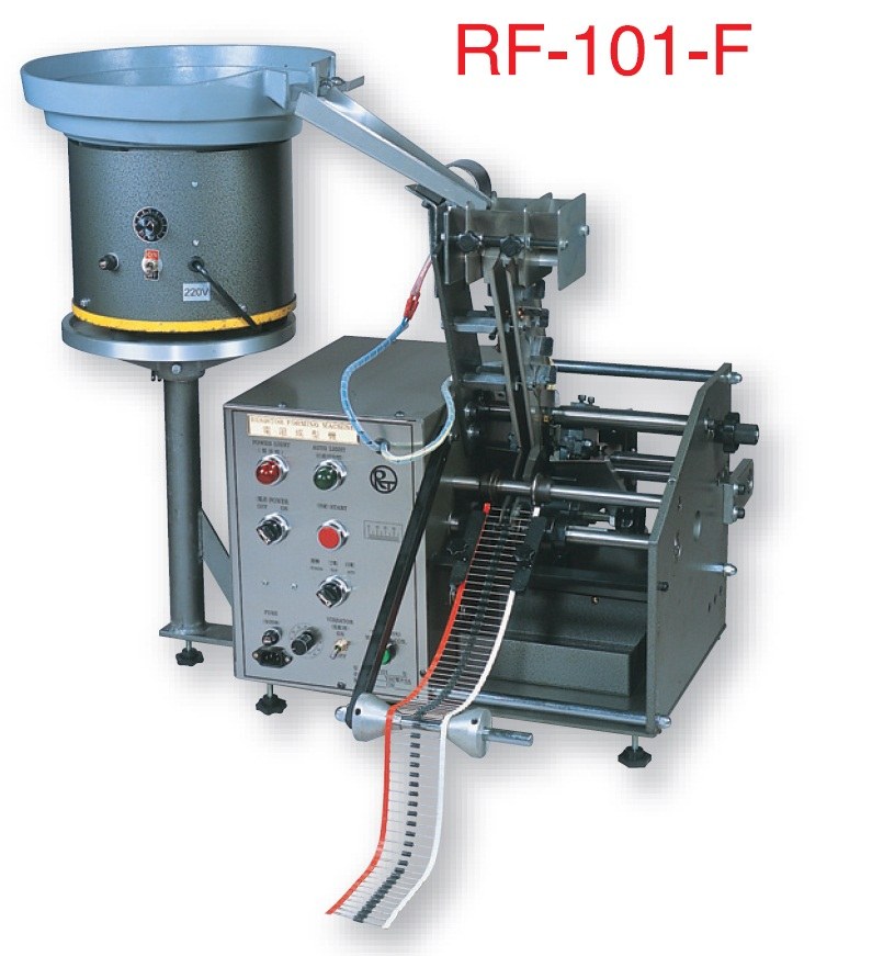
- Versatile feeding options: Dual loose/taped (RF-101C), Loose-only (RF-101CA), and Taped-only (RF-101CB).
- High throughput of 110 pcs/min (6,600 pcs/hr); vibratory bowl holds up to 600 loose components per loading.
- Accommodates component body length 3.8~20 mm, body diameter 2.3~8 mm, and wire diameter Ø0.6~Ø1.3 mm.
【Revision Notes】 打扁模具設計(固定打扁高度 F=2mm);入料模式分為散帶合併款 (RF-101C)、散裝款 (RF-101CA) 與帶裝款 (RF-101CB)。
Lead Forming & Geometric Parameter Specifications
Unit: mm / Custom tooling available Dimension & Bending Schematic RF-101C
Callouts match specifications in the table (Click image to enlarge)
| Code | Parameter | Standard Value / Range | Engineering Notes |
|---|---|---|---|
| A_BODY | Body Length (A) | 3.8 ~ 20 mm | Resistor, diode, inductor body length |
| B_DIA | Body Diameter (B) | 2.3 ~ 8 mm | Suitable for 1/8W ~ 5W various types of component body diameters |
| C_SHOULDER | Shoulder (C) | > 1.2 mm | Safety distance between the bending point and the component body |
| D_HEIGHT | Forming Height (D) | 固定數值 (Fixed at 8mm or custom) | Key fixing height set according to the forming tooling |
| E_LEAD | Lead Length (E) | 可調 (Adjustable) | Fine adjustment of lead length after cutting |
| F_PUNCH | Punching Height (F) | 固定 2 mm (Fixed 2mm) | Lead flattening positioning step height |
| S_SUPPORT | Supporting Point (S) | W + 0.4 ~ 1.5 mm | Flattening bump width, expand according to wire diameter W |
| L_PITCH | Lead Pitch (L) | A + 2C | PCB board span, equal to body length plus shoulder distance on both sides |
| W_WIRE | Wire Diameter (W) | Ø0.6 ~ Ø1.3 mm | Special wire diameter range for flattening forming tooling |
SERIES COMPARISON MATRIX
• Catalog P.06 Reference
RF / HRFT Series Axial Lead Bending & Forming Capabilities Matrix
Comprehensive dimension limits and capacity comparison across Slim, Standard, Heavy Duty, Vertical, and Cut Only models
U_BEND
Horizontal U-Bend
V_BEND
Vertical Stand-off
CUT_ONLY
Straight Cut Only
| Parameters / Models | Slim
Manual: HRFT-301S
Motorized: RFT-201S | Standard
Manual: HRFT-301U
Motorized: RFT-201U | Heavy Duty
Manual: —
Motorized: RFT-201W | Vertical
Manual: HRFT-301F
Motorized: RFT-201F | Cut Only
Manual: HRFT-301L
Motorized: RFT-201L |
|---|---|---|---|---|---|
| A Pitch (Body Length for F) | 5 ~ 40 mm | 6 ~ 40 mm | 6 ~ 40 mm | 4 ~ 18 mm | 3.5 ~ 37.6 mm |
| B Lead Length | 3.6 ~ 10 mm | 3.6 ~ 10 mm | 3.6 ~ 10 mm | 可調 Adjustable | — |
| C Shoulder | > 0.6 mm | > 1.2 mm | > 1.2 mm | > 4 mm | > 3 mm |
| D Body Diameter | Ø1.5 ~ Ø8 mm | Ø1.5 ~ Ø8 mm | Ø1.5 ~ Ø8 mm | Ø1.5 ~ Ø8 mm | Ø1.5 ~ Ø8 mm |
| H Support Length | — | — | — | < 25 mm | — |
| W Lead Wire Diameter | Φ0.35~0.6 / Φ0.35~0.8 mm | Φ0.35 ~ 0.8 mm | Φ0.35 ~ 1.3 mm (粗線徑) | Φ0.35 ~ 0.8 mm | Φ0.35~0.6 / Φ0.35~0.8 mm |
| P Pitch | — | — | — | 2.5 ~ 13.5 mm | — |
| R Bending Angle | — | — | — | 1° (直立折彎) | — |
| CAP Motorized Capacity | 40,000 pcs/H | 84,000 pcs/H (超高速) | 40,000 pcs/H | 40,000 pcs/H | 40,000 pcs/H |
OPTIONAL TOOLING
E63 Pitch Gauge (Optional Accessory)
E63-pitch gauge can be purchased optionally for U/S/W shape bending series to verify PCB hole pitch quickly.
TECHNICAL DOCUMENTATION
View All Technical Documents →
Technical Documents & User Manuals
Digital manuals for this machine are being archived. Please email engineering for direct documentation. Request Manual →
GENUINE CONSUMABLES
View All Spare Parts →
Recommended Genuine Consumables & Spare Parts
Genuine replacement blades, belts, and dies are kept in stock for this machine line. Browse Parts Catalog →